English
 русский
 عربى
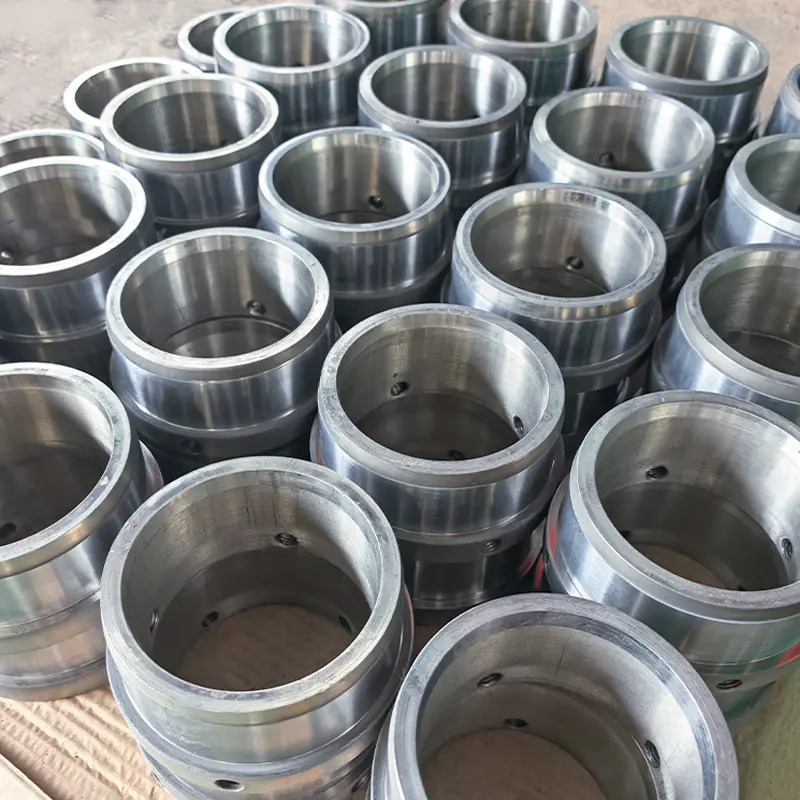
Wear-Resistant Carbide Bushings Customized
The bushings are customized products according to ...
View more
The bushings are customized products according to ...
View more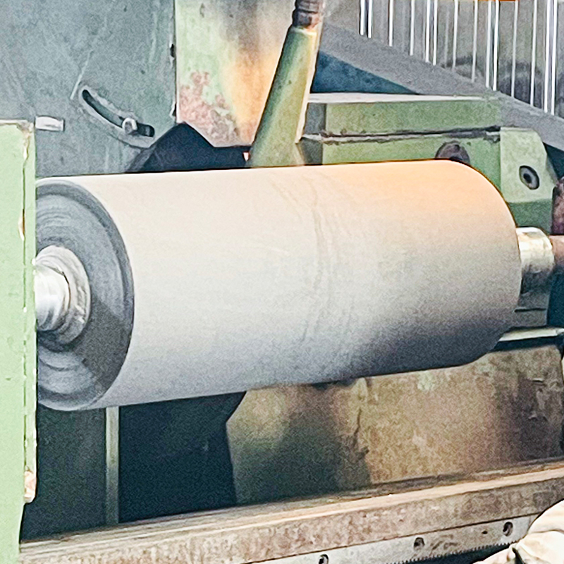
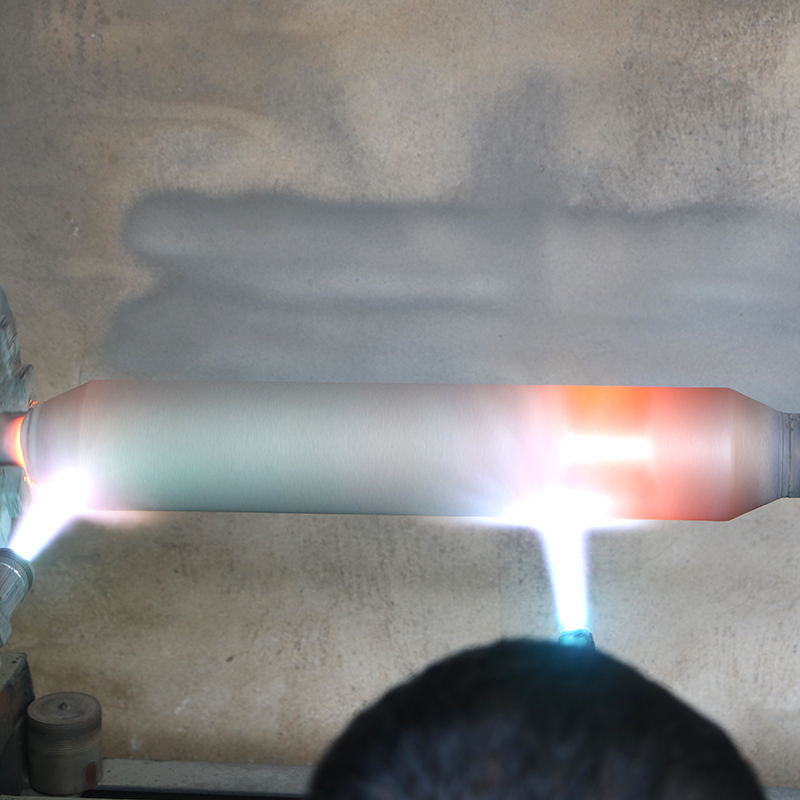
The Customized Tungsten Carbide Coated Roller is e...
View more
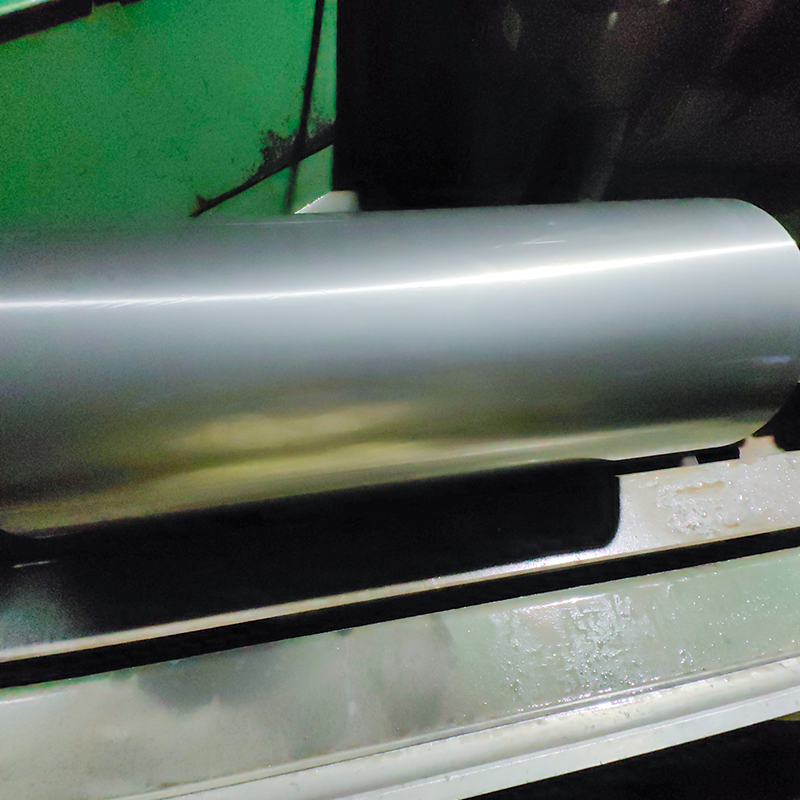
The Customized Laminar Flow Roller with Nickel Bas...
View more
Every rolling mill operates under a unique combina...
View more
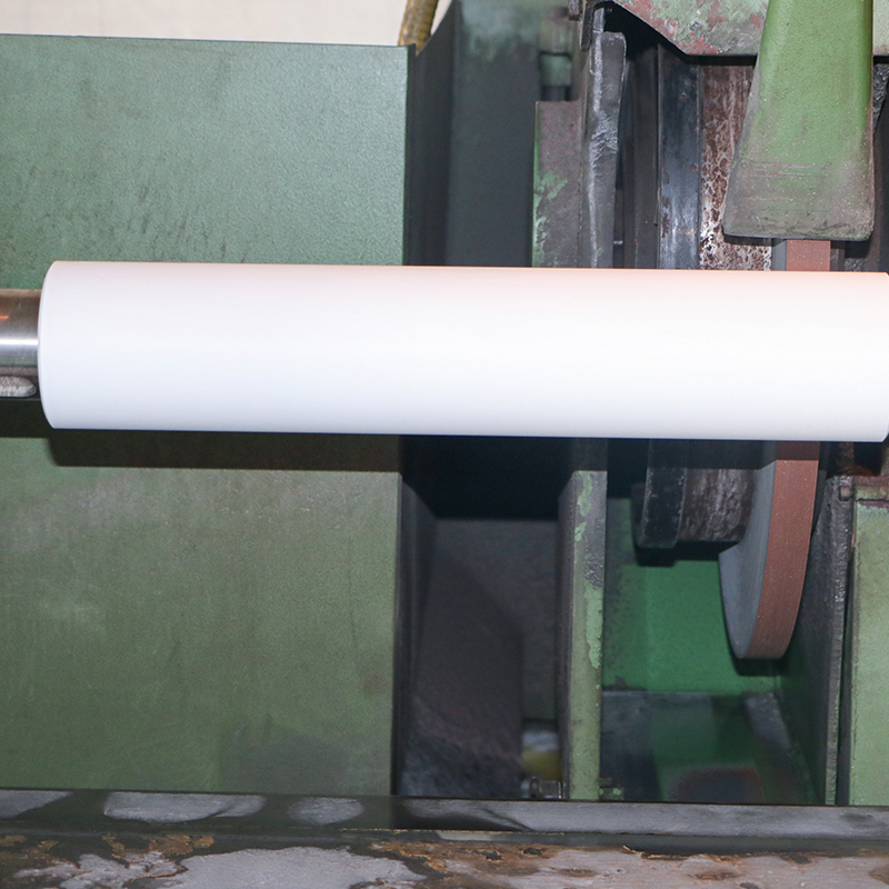
A mirror roller that has lost its surface quality ...
View more
A guide roller that scratches the sheet it carries...
View moreJiangsu Crystal Additive Manufacturing Co., Ltd. was founded in 2010 as a manufacturer of hard-faced wear-resistant rollers, shafts, bushings, plungers, and spiral shafts. We specialize in producing all kinds of metallurgical rollers, paper-making rollers, printing rollers, roughing rollers, mirror rollers, roughing rollers, tungsten carbide coated rollers, ceramic-coated rollers, nickel-based alloy spray welded rollers, shaft sleeves, tungsten carbide shaft sleeves, ceramic shaft sleeves, nickel-based alloy shaft sleeves, cobalt-based alloy shaft sleeves, tungsten carbide plungers, ceramic plungers, nickel-based alloy plungers, cobalt-based alloy plungers, tungsten carbide precision spiral shafts, ceramic precision spiral shafts, etc. We have all kinds of lathes, grinders, milling machines, dynamic balancing machines, and other equipment and equipment. The company has all kinds of lathes, grinding machines, milling machines, dynamic balancing machines, all kinds of advanced coating production equipment technology, all kinds of coating testing equipment, welcomes new and old customers to come to negotiate business!


Anyone who has spent years standing next to a powder bed will tell you the same thing: the machine gets the attention, but the powder decides the out...
READ MOREAdditive manufacturing powder looks simple from a distance: fine metal particles, a hopper, a build plate, and a finished part. Up close, it is a car...
READ MORECobalt based alloy powder rarely gets much attention until a part stops working. Over the years we have seen it rescue valve seats that were being re...
READ MOREChromium oxide ceramic powder is one of those materials that rarely makes headlines but quietly keeps a great deal of industrial equipment running. I...
READ MOREAsk five people on a plant floor what ceramic powder means and you may get five different answers. To a potter it is the raw material behind a glaze....
READ MOREIndustry Knowledge Expansion
Most premature failures of wear-resistant rollers come from choosing a coating by hardness alone. A roller that fails by abrasion, adhesion, impact or hot corrosion needs a different microstructure in each case. In hot rolling and conveying lines, for example, a very hard but brittle iron-based overlay may spall within weeks, while a tougher cobalt-based layer with a moderate hardness of 38 to 48 HRC survives thermal cycling far longer. Identifying the dominant wear mode first saves repeated downtime and rework.
The table below summarizes a practical starting point. Final selection should always be confirmed against the operating temperature, the counter-material and the base metal of the roller body.
| Dominant Wear Mode | Typical Working Condition | Recommended Powder Family | Typical Hardness |
| Severe abrasion | Sand, ore, ceramic or glass contact | NiCrBSi + 35-60% tungsten carbide | 58-65 HRC (matrix) |
| Thermal fatigue and oxidation | Hot strip, 500-800 °C | Cobalt-based (Stellite-type) | 38-50 HRC |
| Adhesive wear and galling | Metal-to-metal sliding | Copper-based or cobalt-based | 25-45 HRC |
| Impact plus moderate abrasion | Crushing and feeding rolls | Iron-based Fe-Cr-C / Fe-Cr-B | 50-62 HRC |
| Corrosion plus wear | Chemical, paper and pulp rolls | Nickel-based (Ni-Cr-Mo-W type) | 30-45 HRC |
As a powder manufacturer, we can supply these families in standard grades and also adjust composition for a specific roller duty cycle.
Industrial rollers range from slender printing rollers of 100 mm diameter to steel mill rolls weighing several tons, and the deposition process must suit the geometry and the allowable heat input. Each process also calls for a different powder particle size distribution, so the powder and the process should be selected together rather than separately.
| Process | Typical Powder Size | Dilution Rate | Layer Thickness per Pass | Bond Type |
| Laser cladding | 45-150 μm | Below 5% | 0.3-2.0 mm | Metallurgical |
| Plasma transferred arc (PTA) | 53-180 μm | 5-15% | 1.0-4.0 mm | Metallurgical |
| HVOF spraying | 15-45 μm | None | 0.1-0.5 mm | Mechanical |
Laser cladding is usually preferred for precision rollers because low heat input keeps distortion within a few hundredths of a millimeter and preserves the base metal properties. PTA suits large-diameter rolls that need thick overlays in fewer passes. HVOF is best when the dimensional tolerance is tight and a thin, dense carbide coating followed by grinding is enough, but it relies on mechanical bonding, so it is less suited to heavy impact loads.
A wear-resistant spiral shaft, as used in screw conveyors, extruders and feeders, is difficult to clad because the helical flight has a thin, high-aspect-ratio cross section that heats up and cools unevenly. Cracks usually appear at the flight root or along the flight edge, where residual tensile stress concentrates. Three variables control most cracking problems: the carbon equivalent of the base steel, the hardness gap between coating and substrate, and the cooling rate after deposition.
Straightening after cladding should be done below the coating's strain tolerance. Cold-straightening a fully hardened carbide layer is a common cause of late-appearing cracks, so it is better to control distortion through balanced deposition sequences from the start.
Two powders with the same nominal composition can produce very different coatings. When evaluating a powder for rollers or shafts, it is worth requesting data for the following indicators rather than relying on the grade name alone.
| Indicator | Typical Target | Effect if Out of Range |
| Hall flow rate (50 g) | Below 18 s | Unstable feeding, uneven bead height |
| Oxygen content | Below 300 ppm for gas-atomized powder | Porosity and oxide inclusions |
| Sphericity | Above 90% spherical particles | Poor flowability, clogged nozzles |
| Satellite and hollow particles | Minimal | Internal gas pores in the clad layer |
| Moisture | Below 0.05% | Spatter and hydrogen-related defects |
Even a good powder absorbs moisture in humid workshops, so drying it at 100-120 °C for 1-2 hours before use is a low-cost habit that noticeably reduces porosity in the finished layer.
Reclaiming Industrial Rollers is usually far cheaper than replacement, but only if the base body is sound. A systematic inspection before machining and cladding prevents wasted effort on rolls that cannot be saved.
After cladding, ultrasonic or eddy current inspection of the bond line is advisable for rolls in critical service, and hardness should be checked at both ends and at the center to confirm uniformity.
Wear along a screw or spiral shaft is rarely uniform. The feed zone sees coarse, loosely packed material and suffers the heaviest abrasion on the flight's pushing face, while the compression and discharge zones face higher pressure and temperature. Applying the same premium coating over the entire length is often wasteful, and it can even be counterproductive when a brittle layer is placed where impact dominates.
A zoned approach assigns the hardest tungsten carbide composite overlay to the flight tips and pushing faces, a tougher nickel-based or cobalt-based alloy to the flight root and shaft core, and a corrosion-resistant grade where moisture or chemical media are present. Tip clearance should also be considered: a hard-faced flight tip typically keeps the barrel gap stable for two to four times longer than an uncoated one, which maintains throughput and reduces back-flow losses. Our team can recommend a layered powder combination for a given shaft drawing and material type.


 Bianzhuang Industrial Concentration Zone, Yuxi, Jiangyan District, Jiangsu Province
 +86-0523-86505558 / +86-0523-86506668
 +86-13961019985 / +86-18852676660
 [email protected]
Copyright ©Jiangsu Crystal Additive Manufacturing Co., Ltd. All Rights
Reserved.
 Wear-resistant Roller Solution