

 English
 русский
 عربى
Product Category
Download
Ceramic Spiral Shaft Company
ABOUT US
JIANGSU CRYSTAL ADDITIVE
MANUFACTURING CO., LTD.
Jiangsu Crystal Additive Manufacturing Co., Ltd. is China Ceramic Spiral Shaft Company and High Precision Spiral Shaft Solution specializing in R&D,
production and sales of various types of (cobalt-based, nickel-based,
copper-based, iron-based, high-temperature alloy and composite tungsten
carbide powder) alloy powders that can be used in various application
processes.
Powder, (can be customized pure nickel powder, pure cobalt powder, pure copper powder, etc.) metal powder.
We offer High Precision Spiral Shaft. We are always committed to developing and producing various high-performance alloy materials for harsh environments, providing customers with high-strength, wear-resistant, corrosion-resistant and high-temperature-resistant alloy powders.
Powder, (can be customized pure nickel powder, pure cobalt powder, pure copper powder, etc.) metal powder.
We offer High Precision Spiral Shaft. We are always committed to developing and producing various high-performance alloy materials for harsh environments, providing customers with high-strength, wear-resistant, corrosion-resistant and high-temperature-resistant alloy powders.
Corporate Promotional Video

WAS FOUNDED IN
Our Factory


News
-
From Spec Sheet to Build Plate: Selecting Alloy Powders for Additive Manufacturing
Anyone who has spent years standing next to a powder bed will tell you the same thing: the machine gets the attention, but the powder decides the out...
READ MORE -
Additive Manufacturing Powder: A Practical Guide to Metal Powder Selection
Additive manufacturing powder looks simple from a distance: fine metal particles, a hopper, a build plate, and a finished part. Up close, it is a car...
READ MORE -
Cobalt Based Alloy Powder: A Practical Guide to Grades, Properties, and Selection
Cobalt based alloy powder rarely gets much attention until a part stops working. Over the years we have seen it rescue valve seats that were being re...
READ MORE -
Chromium Oxide Ceramic Powder: Properties, Grades and Coating Applications
Chromium oxide ceramic powder is one of those materials that rarely makes headlines but quietly keeps a great deal of industrial equipment running. I...
READ MORE -
Ceramic Powder: Types, Properties, and How to Choose the Right Grade for Your Parts
Ask five people on a plant floor what ceramic powder means and you may get five different answers. To a potter it is the raw material behind a glaze....
READ MORE
Industry Knowledge Expansion
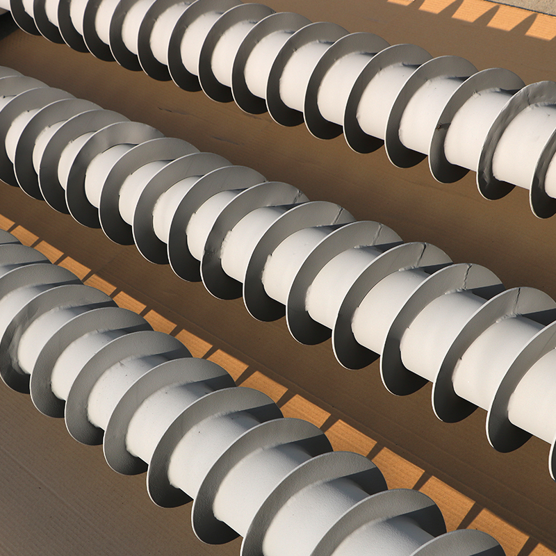
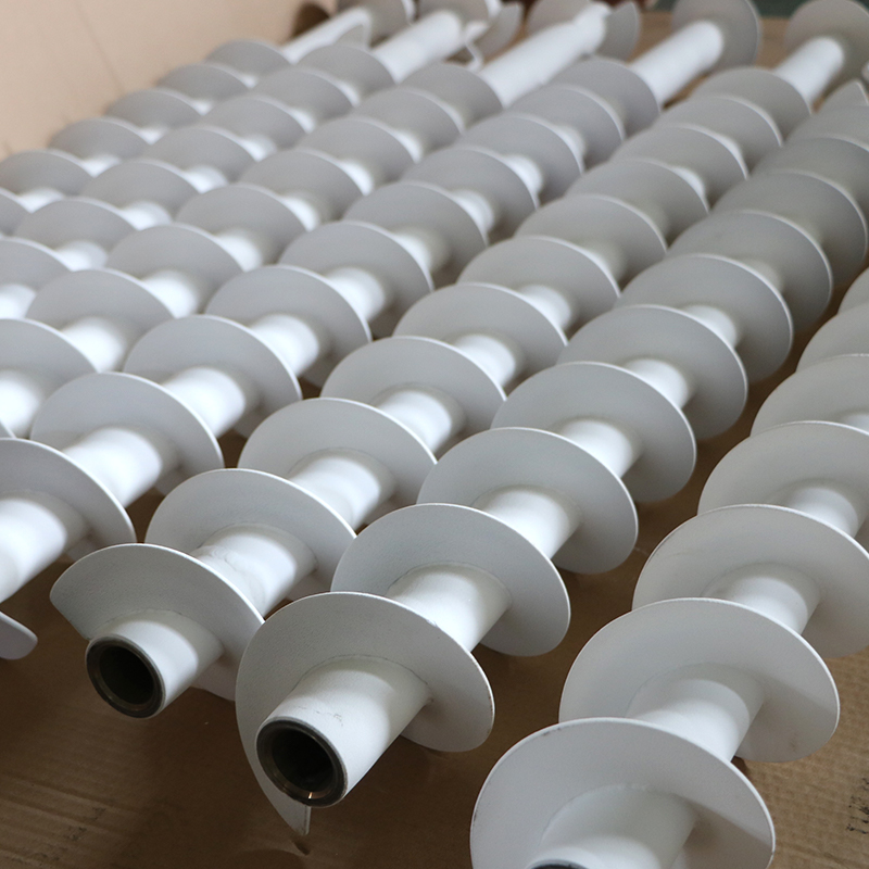
How to Choose the Right Ceramic Material for a Ceramic Spiral Shaft
A Ceramic Spiral Shaft is rarely made from "just ceramic". The base material decides how long the shaft survives against abrasive powders, corrosive slurries or high operating temperatures. Alumina is the most common choice because it is hard and cost-effective. Zirconia is selected when impact or shock loads are expected, since its fracture toughness is much higher. Silicon nitride suits high-speed rotation and thermal cycling, while silicon carbide is preferred for strongly acidic or alkaline media and for applications that need good heat dissipation.
| Material | Typical Density (g/cm³) | Key Strength | Best Suited For |
| Alumina (95%–99.7%) | 3.7–3.95 | Wear resistance, low cost | Abrasive powder conveying, dosing |
| Zirconia (Y-TZP) | about 6.0 | High toughness and bending strength | Shock loads, thin-walled or slender shafts |
| Silicon Nitride | about 3.2 | Thermal shock resistance, light weight | High-speed or high-temperature rotation |
| Silicon Carbide | about 3.1 | Extreme hardness, chemical inertness | Corrosive media, abrasive slurries |
As a rule of thumb, start from the failure mode you want to eliminate (abrasion, corrosion, thermal shock or breakage) and then pick the ceramic that addresses it, rather than defaulting to the hardest material available.
Which Tolerances Actually Matter on a High Precision Spiral Shaft
Many drawings for a High Precision Spiral Shaft over-specify every dimension, which raises cost without improving performance. In practice, only a few parameters control conveying stability and dosing accuracy. Cumulative lead (pitch) error determines whether material is delivered at a constant rate per revolution. Flight thickness and root diameter control the effective cavity volume. Straightness and runout of the journal sections determine how evenly the shaft runs inside its barrel or sleeve.
Parameters worth specifying carefully
- Lead error: typically held within ±0.02–0.05 mm per 100 mm for precision dosing, depending on shaft length and pitch.
- Journal runout: usually 0.01–0.02 mm, which keeps the radial clearance to the barrel uniform around the circumference.
- Flight surface roughness: Ra 0.4–0.8 μm on the conveying faces reduces powder adhesion and bridging.
- Straightness: critical for slender shafts with a length-to-diameter ratio above 10, where small bends cause cyclic rubbing.
Dimensions such as chamfers, non-working end faces and keyway widths can generally follow standard ceramic tolerances, which saves grinding time and reduces rejection rates.
Green Machining vs. Hard Grinding: How Spiral Geometry Is Formed in Ceramics
The thread form on a ceramic shaft can be created at two stages, and each has clear trade-offs. In green machining, the spiral is cut into the pre-sintered blank while it is still relatively soft. This is fast and economical, but the part then shrinks by roughly 15%–20% during sintering, so lead and diameter must be compensated in advance and some distortion is unavoidable. In hard grinding, the sintered blank is ground with diamond tools. It takes longer and costs more, but it is the only reliable way to reach tight lead accuracy and a smooth flight surface.
A common compromise is to green-machine the rough profile with 0.2–0.4 mm of stock left on the working surfaces, then finish-grind only the flights and journals after sintering. This keeps cost under control while still delivering the accuracy expected of a High Precision Spiral Shaft.
Setting the Radial Clearance Between Shaft and Barrel
Clearance is one of the most overlooked variables in screw dosing and conveying. If it is too large, fine powder leaks backwards through the gap and the feed rate drifts, especially at low speeds. If it is too small, thermal expansion or a few oversized particles can cause jamming, and ceramics do not yield the way metals do, so contact usually ends in chipping. Because ceramic expands far less than steel, a ceramic shaft inside a metal barrel will open up its clearance as the system heats, a point that is easy to miss during design.
- Fine powders (D50 below 30 μm): start with a clearance of about 0.05–0.10 mm.
- Medium powders (D50 30–100 μm): about 0.10–0.20 mm is generally workable.
- Operating above 200 °C: calculate the expansion difference between shaft and barrel at working temperature before fixing the cold clearance.
Ceramic Shaft or Coated Metal Shaft: A Practical Selection Guide
A Ceramic Spiral Shaft is not always the best answer. For long or heavily loaded shafts, a steel core carrying a thermally sprayed or laser-clad wear layer can be more economical and far less brittle. Cobalt-based alloys and tungsten carbide composite coatings are widely used on screw flights for this purpose, and at Jiangsu Crystal Additive Manufacturing we supply the alloy powders for exactly these cladding and spraying routes, which makes it easy to compare both options for the same application.
| Factor | Ceramic Spiral Shaft | Coated Metal Shaft |
| Abrasion resistance | Excellent throughout the whole body | Excellent, but limited to the coating thickness |
| Impact tolerance | Low to moderate (zirconia is better) | High, thanks to the tough steel core |
| Corrosion resistance | Excellent, no metal contamination | Depends on coating density and alloy choice |
| Repairability | Replace only | Can be stripped and re-coated |
| Best fit | Contamination-sensitive, corrosive or abrasive duty | Long shafts, heavy torque, shock loads |
Common Failure Modes of Ceramic Spiral Shafts and How to Prevent Them
Most field failures can be traced back to installation or operating conditions rather than to material defects. Recognizing the fracture pattern often tells you the cause.
Typical problems and their usual causes
- Fracture at the shaft shoulder: stress concentration from a sharp inner corner. Specifying a generous fillet radius (at least 0.5–1.0 mm) greatly reduces the risk.
- Chipped flight edges: hard foreign particles or contact with the barrel. Installing a screen upstream and checking runout at assembly usually solves it.
- Cracking at the drive end: rigid metal-to-ceramic clamping without a compliant interlayer. A sleeve, gasket or elastic coupling distributes the load.
- Thermal shock cracks: sudden start-up with hot or cold material. A gradual warm-up, ideally below 100 °C per minute, protects the shaft.
Keeping a simple log of start-up procedure, material batch and running hours makes it much easier to identify the pattern behind repeated failures.
Incoming Inspection Checklist for a High Precision Spiral Shaft
Before a High Precision Spiral Shaft goes into production equipment, a short inspection routine can prevent costly downtime. Begin with a visual check under good lighting for micro-cracks, especially at the roots of the flights and at shoulders; a dye penetrant test can reveal fine surface cracks that are invisible to the eye. Next, mount the shaft between centers and measure runout at several points along its length. Then measure the outer diameter and lead on a coordinate or thread measuring machine, comparing results to the drawing tolerance rather than to nominal values only. Finally, weigh the shaft and compare it with the expected mass based on density, since an unusually low value may point to excessive porosity.
Recording these baseline values also gives you a reference for later wear measurements, so you can predict the replacement interval instead of waiting for performance to drop.


CONTACT US
GET PRODUCT CATALOG,
SERVICE INTRODUCTION AND QUOTATION
-
 Bianzhuang Industrial Concentration Zone, Yuxi, Jiangyan District, Jiangsu Province
-
 +86-0523-86505558 / +86-0523-86506668
-
 +86-13961019985 / +86-18852676660
-
 [email protected]
Copyright ©Jiangsu Crystal Additive Manufacturing Co., Ltd. All Rights
Reserved.
 Ceramic Spiral Shaft Solution