English
 русский
 عربى
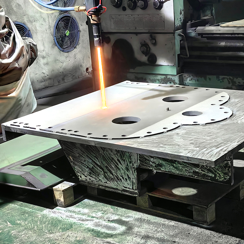
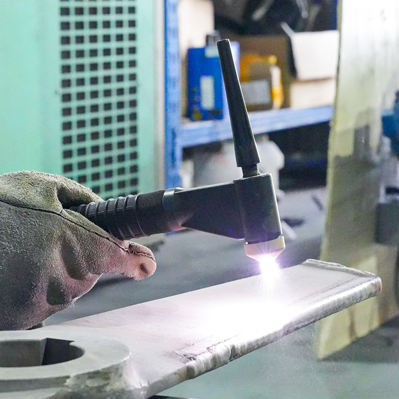
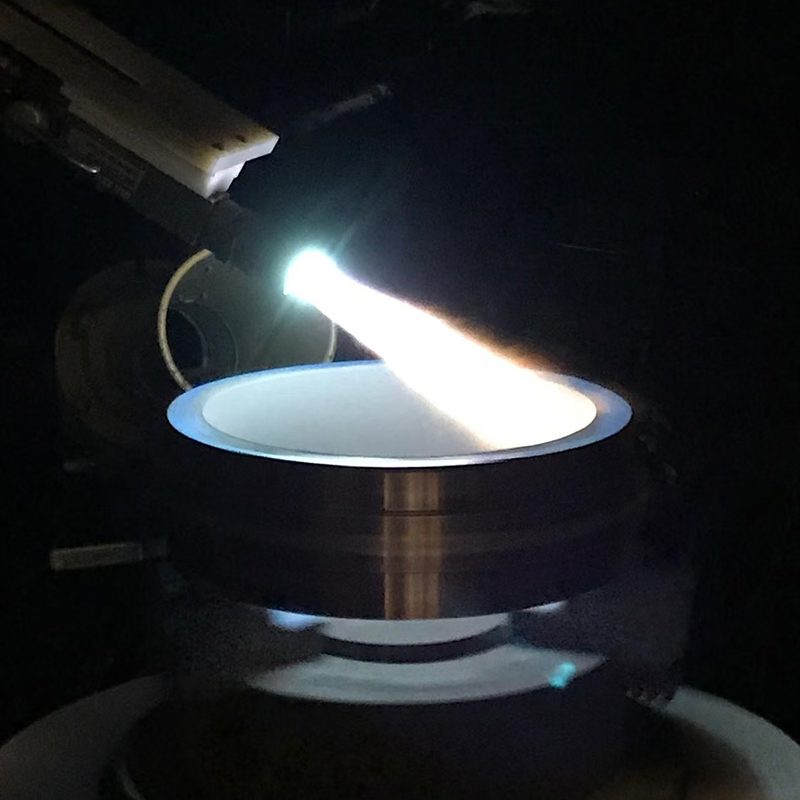
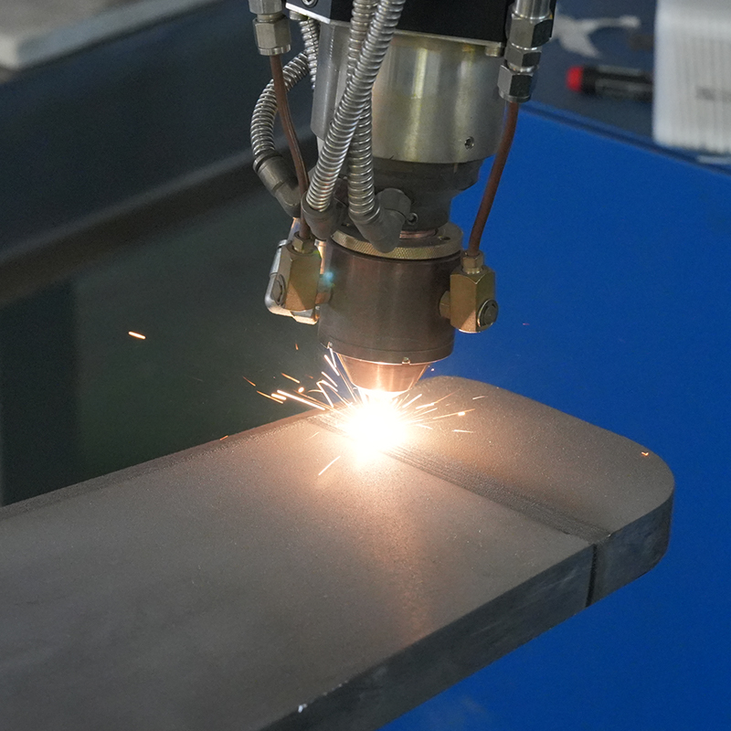
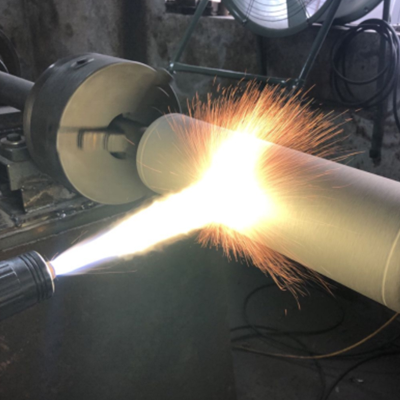
Supersonic Spraying
The supersonic flame spraying process uses fuel (h...
View moreJiangsu Crystal Additive Manufacturing Co., Ltd. was founded in 2010 as a manufacturer of hard-faced wear-resistant rollers, shafts, bushings, plungers, and spiral shafts. We specialize in producing all kinds of metallurgical rollers, paper-making rollers, printing rollers, roughing rollers, mirror rollers, roughing rollers, tungsten carbide coated rollers, ceramic-coated rollers, nickel-based alloy spray welded rollers, shaft sleeves, tungsten carbide shaft sleeves, ceramic shaft sleeves, nickel-based alloy shaft sleeves, cobalt-based alloy shaft sleeves, tungsten carbide plungers, ceramic plungers, nickel-based alloy plungers, cobalt-based alloy plungers, tungsten carbide precision spiral shafts, ceramic precision spiral shafts, etc. We have all kinds of lathes, grinders, milling machines, dynamic balancing machines, and other equipment and equipment. The company has all kinds of lathes, grinding machines, milling machines, dynamic balancing machines, all kinds of advanced coating production equipment technology, all kinds of coating testing equipment, welcomes new and old customers to come to negotiate business!


Anyone who has spent years standing next to a powder bed will tell you the same thing: the machine gets the attention, but the powder decides the out...
READ MOREAdditive manufacturing powder looks simple from a distance: fine metal particles, a hopper, a build plate, and a finished part. Up close, it is a car...
READ MORECobalt based alloy powder rarely gets much attention until a part stops working. Over the years we have seen it rescue valve seats that were being re...
READ MOREChromium oxide ceramic powder is one of those materials that rarely makes headlines but quietly keeps a great deal of industrial equipment running. I...
READ MOREAsk five people on a plant floor what ceramic powder means and you may get five different answers. To a potter it is the raw material behind a glaze....
READ MOREIndustry Knowledge Expansion
Laser cladding and plasma spray coating are often discussed as competitors, but they solve different problems. Laser cladding melts the powder and a thin layer of the substrate into a true metallurgical bond, with dilution typically held between 1% and 10%. Plasma spray coating projects molten or semi-molten particles onto a roughened surface, so adhesion is mechanical and the bond strength usually falls in the 20–40 MPa range. The first suits heavily loaded, impact-exposed parts. The second suits parts that need a thin, hard, thermally or electrically insulating surface without distorting the base metal.
| Item | Laser Cladding | Plasma Spray Coating |
| Bond type | Metallurgical | Mechanical interlocking |
| Typical thickness | 0.3–3 mm per layer | 0.05–0.5 mm |
| Porosity | Close to zero | 1%–5% |
| Heat input to part | Low and localized | Low, part temperature kept below about 150 °C |
| Suitable materials | Metal and metal-carbide alloys | Metals, carbides and ceramics |
| Best for | Hydraulic rods, rolls, valve seats, drill tools | Pump sleeves, insulation layers, thermal barriers |
As a rule of thumb, if the part will see impact, heavy contact stress or corrosion through the coating, choose laser cladding. If the part is thin-walled, heat-sensitive or needs a ceramic surface, choose plasma spray coating.
Most plasma ceramic coating failures are traced back to preparation and thermal mismatch rather than the ceramic powder itself. Ceramics such as Al₂O₃ expand at roughly 7–8 ×10⁻⁶/K, while carbon steel expands at about 12 ×10⁻⁶/K. The gap builds stress at the interface every time the part heats and cools.
For material choice, Al₂O₃–13%TiO₂ is a tough, economical option for wear and insulation (about 800–1000 HV). Cr₂O₃ reaches roughly 1200–1400 HV for fine sliding wear, and 7–8 wt% Y₂O₃-stabilized zirconia is used for thermal barriers. We supply plasma-grade powders in controlled size ranges so that your spray parameters stay repeatable from lot to lot.
Particle size distribution decides whether a powder feeds smoothly and melts correctly. A powder that is too fine clogs the feed line and vaporizes in the beam or plume. A powder that is too coarse stays unmelted and leaves voids. The ranges below are typical starting points and should be fine-tuned to your equipment.
| Process | Typical Size Range | Feeding Note |
| Coaxial laser cladding | 53–150 µm | Spherical powder with good flowability for stable feed |
| High-speed laser cladding | 15–53 µm | Fine, narrow distribution for thin, smooth layers |
| Plasma spray (metal and alloy) | 45–106 µm | Match to plasma power and spray distance |
| Plasma spray (ceramic) | 15–45 µm | Fused-and-crushed or agglomerated powder for dense melting |
Flowability is just as important as size. A Hall flow time under about 20 s/50 g for alloy powders generally indicates stable feeding, and satellite-free spherical particles from gas atomization help keep the feed rate steady over long cladding runs.
High-hardness cobalt-based and nickel-based layers, especially those loaded with tungsten carbide, are prone to cracking on carbon and alloy steels because of the steep thermal gradient between the melt pool and the cold substrate. Cracks usually appear when layer hardness exceeds about 55–60 HRC with no stress relief. Several adjustments help in practice.
If dilution rises above 10%, the iron pick-up lowers the layer's corrosion and hardness performance. Reduce laser power or increase scanning speed rather than simply cutting the powder feed rate. When a project calls for a specific composition, we can customize cobalt-based, nickel-based, copper-based or iron-based powders to fit it.
Moisture is a frequent, overlooked source of porosity in both cladding and thermal spray layers. Fine alloy powders absorb humidity quickly, and the water turns to steam in the melt pool, leaving pinholes. Ceramic powders are especially sensitive because their porous particles hold more moisture.
Following this routine costs little and often removes the need to chase porosity through laser or plasma parameter changes. We are happy to share batch data and recommended drying conditions with each order.


 Bianzhuang Industrial Concentration Zone, Yuxi, Jiangyan District, Jiangsu Province
 +86-0523-86505558 / +86-0523-86506668
 +86-13961019985 / +86-18852676660
 [email protected]
Copyright ©Jiangsu Crystal Additive Manufacturing Co., Ltd. All Rights
Reserved.
 Plasma Spray Coating Solution