English
 русский
 عربى
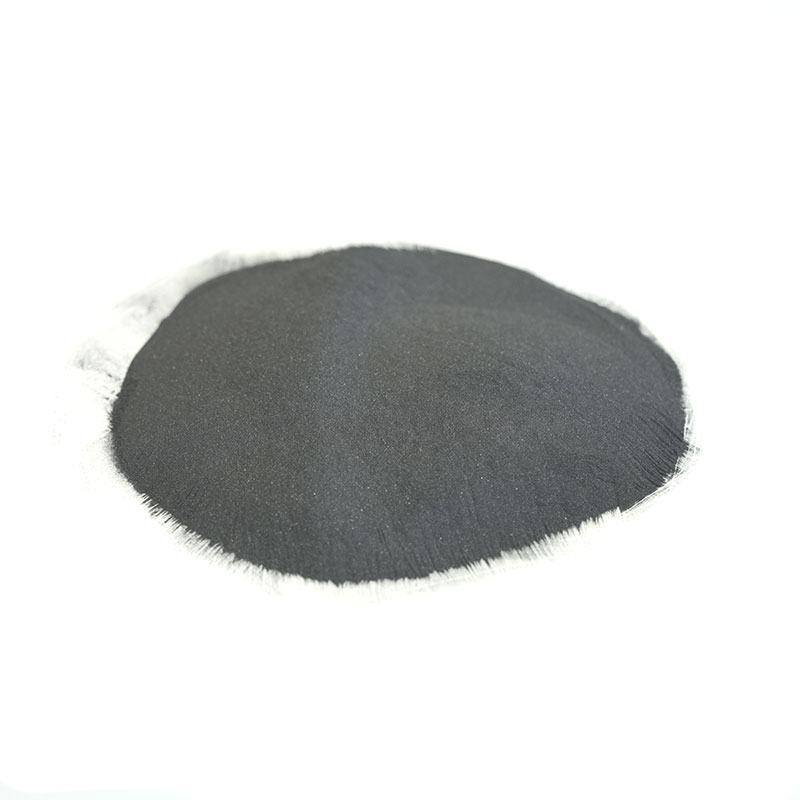
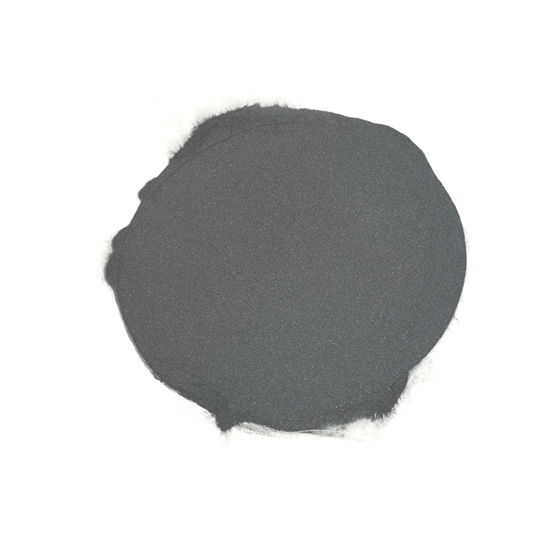
Tungsten Carbide Thermal Spray Powder
Composite carbide alloys are designed to meet the ...
View more
Composite carbide alloys are designed to meet the ...
View moreCarbide metal powder is composed of metal and carbon elements, and has properties such as good corrosion resistance, high-temperature strength, and hardness.
Application of carbide metal powder:
1. Powder metallurgy field
By adjusting different proportions of carbide metal powder, composite materials with different properties can be prepared, such as high hardness, high wear resistance, high strength, and other composite materials, which are used in the manufacture of molds, cutting tools, bearings, and other parts.
2. Surface strengthening field
Such as surface hardening, surface wear resistance, surface corrosion resistance, etc. This surface strengthening technology can be used for surface processing of parts, such as punching dies, extrusion dies, high-speed cutting tools, and other fields.
3. Composite material field
Carbide metal powder is compounded with other materials to form a new composite material with mechanical properties and material properties. This composite material can be used in the manufacture of aerospace, automotive parts, and other fields.


Anyone who has spent years standing next to a powder bed will tell you the same thing: the machine gets the attention, but the powder decides the out...
READ MOREAdditive manufacturing powder looks simple from a distance: fine metal particles, a hopper, a build plate, and a finished part. Up close, it is a car...
READ MORECobalt based alloy powder rarely gets much attention until a part stops working. Over the years we have seen it rescue valve seats that were being re...
READ MOREChromium oxide ceramic powder is one of those materials that rarely makes headlines but quietly keeps a great deal of industrial equipment running. I...
READ MOREAsk five people on a plant floor what ceramic powder means and you may get five different answers. To a potter it is the raw material behind a glaze....
READ MOREIndustry Knowledge Expansion
The same Carbide Powder can perform very differently depending on whether its size distribution suits the deposition process. HVOF and HVAF systems need fine, narrow cuts so particles fully heat and accelerate in a short dwell time. Laser cladding and PTA welding use coarser cuts, because the powder is fed into a melt pool and fine particles tend to be blown away or vaporized. A mismatch usually shows up as clogged feeders, low deposition efficiency, or an uneven coating surface.
When we produce powders for a specific process, we control both the D10/D50/D90 values and the fines fraction, so the powder feeds consistently from the first hour of a run to the last.
In Carbide Composite Powder, the hard phase (usually tungsten carbide) provides abrasion resistance, while the metallic matrix determines toughness, corrosion resistance, and how well the layer bonds to the substrate. Choosing the matrix is often more important than choosing the carbide fraction, and the table below summarizes the common options.
| Matrix | Strengths | Limitations | Typical Use |
| Cobalt | Excellent wetting of WC, high toughness | Weaker in acidic media | Wear parts, HVOF coatings |
| Cobalt-Chromium | Better oxidation and corrosion resistance | Slightly lower hardness than pure Co | Valves, hydraulic rods |
| Nickel | Good corrosion resistance, good weldability | Lower carbide wetting than Co | Laser cladding, PTA overlay |
| Iron | Lower cost, good for heavy abrasion | Limited corrosion resistance | Mining and earthmoving tools |
Because our range covers cobalt-, nickel-, copper-, and iron-based systems, we can tune the matrix and carbide ratio to your working conditions rather than forcing a standard grade to fit.
When a tungsten carbide-containing Carbide Metal Powder is fed into a laser melt pool, part of the WC dissolves into the liquid metal. The released tungsten and carbon can re-precipitate as brittle phases such as W2C or M6C-type carbides, which increase cracking sensitivity and leave less carbide to resist wear. Dissolution is driven mainly by melt pool temperature and time at temperature, so process parameters matter as much as powder choice.
Two batches of Carbide Composite Powder with identical chemical analysis can behave very differently in the feeder. Flowability depends on particle shape, surface roughness, moisture content, and the fines fraction. Spherical, agglomerated-and-sintered or gas-atomized particles typically flow well, while crushed and angular particles tend to bridge in the hopper and pulse at the nozzle. A pulsing feed creates thickness variation and local porosity in the finished layer.
A simple incoming inspection routine can prevent most feeding problems:
Fine metal powders absorb moisture from the air, and moisture causes clumping, unstable feeding, and hydrogen-related porosity in cladding and welding deposits. Keep sealed containers in a dry, temperature-stable room, and avoid opening a large drum repeatedly; decant working quantities into smaller sealed containers instead. Once a container is open, use it within a reasonable period and reseal it with fresh desiccant.
If powder has picked up moisture, drying at about 100–120 °C for 2–4 hours in a ventilated oven usually restores flow, then let it cool in a sealed container before use. Do not dry powders containing organic binders or coatings at higher temperatures without checking the manufacturer's data. Our powders are supplied in sealed packaging, and we are glad to advise on the correct pre-treatment for your equipment.
Cracking and porosity are the two most common defects in carbide-reinforced layers, and they usually come from a small number of causes. Cracks form when thermal stress exceeds the strength of the matrix, especially with high carbide fractions or a large hardness gap between coating and substrate. Porosity comes from trapped gas, damp powder, or insufficient melt pool stability.


 Bianzhuang Industrial Concentration Zone, Yuxi, Jiangyan District, Jiangsu Province
 +86-0523-86505558 / +86-0523-86506668
 +86-13961019985 / +86-18852676660
 [email protected]
Copyright ©Jiangsu Crystal Additive Manufacturing Co., Ltd. All Rights
Reserved.
 Carbide Composite Powder Company